
1. Gas Permeability
Coating permeability controls the back pressure at the metal front by allowing the gas generated by the pattern degradation to escape the casting cavity. Coating permeability is controlled by the size and number of pores in the coating. The pore size and number of pores is fixed by the coating supplier through his selection of ingredients used to formulate the coating. Coating permeability must be controlled within a narrow range to assure the metal velocity is consistently within the ‘window’ required for minimum casting defects. To achieve consistency coating permeability should be monitored on a schedule consisting of at least once every shift (8 hours) or any time additions are made to the coating tank. Benefits of coating permeability control can be seen in Figure 1.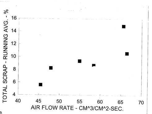
Figure 1-Effect of Coating Permeability on Weekly Scrap Rate

2. Liquid Absorption
Liquid absorption capability of coatings closely follows gas permeability since the pore structure controls both properties. Normally coatings with high gas permeability also have high liquid absorption. Although this property is believed to be important in the filling process of Lost Foam Castings current data does not indicate a strong correlation between casting defects and liquid absorption. The current physical model of metal filling illustrates that liquid island are trapped between the coating and metal after the metal front has passed. These islands of liquid are heated by the metal until they are vaporized with the generated gases pass through the coating. Hence hot gas permeability should control the exodus of liquid components.
3. Thermal Conductivity
Coating thermal conductivity controls the rate of heat removal from the molten metal during the filling process. If the conductivity is high the metal will not flow through long pattern sections before it solidifies, resulting in a misrun. Thermal conductivity of coatings falls into two categories 1.) high and 2.) low. High conductivity coatings are made from granular particles of refractories such as Silica while low conductivity coatings are made from platelet refractories such as Mica (Figure 3). A 40% reduction in thermal conductivity can be achieved by choosing a Mica coating over a Silica coating, however the Mica coatings tend to be lower in gas permeability. Usually, a mixture of particulate and platelet refractories is used to customize coating permeability and thermal conductivity.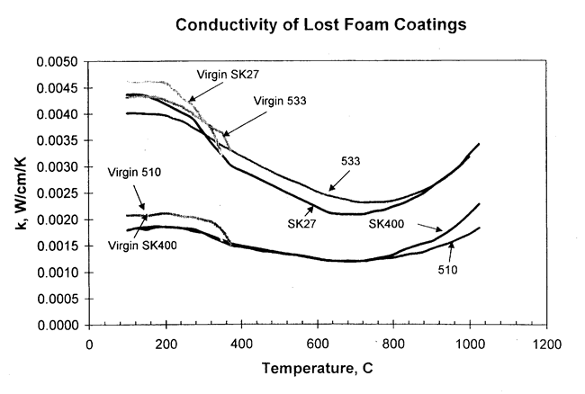
Figure 3 - Thermal Conductivity of Lost Foam Coatings
4. Viscosity
Coating viscosity controls the coating thickness (Figure 4). For this reason, coating viscosity should be determined on a scheduled basis. Coating viscosity in the dip tank can change for several reasons 1.) mixing procedures 2.) water evaporation 3.) water removal by poorly fused patterns 4.) bacterial growth. Procedures for measuring viscosity of coatings have been developed and should be strictly followed.
Figure 4 - Effect of Coating Viscosity on Deposited Thickness
5.Temperature
Since coating viscosity is controlled by temperature it is important to maintain the coating dip tank within a temperature range of 75 F to 85 F range. This will provide consistency in the coating viscosity.
6. Solids Content
Coating’s suppliers use Solids Content of coatings as an indicator of coating rheology. Small changes in Solids Content will not affect coating gas permeability; however, the deposited amount of coating on the pattern will be influenced. Normally when Solids Content increases the coating viscosity will increase. If the reverse trend occurs the coating is usually infected and should be treated or replaced. Solids Content measurements should be a scheduled quality control measure.
Coating Property Measurement Procedures
Permeability

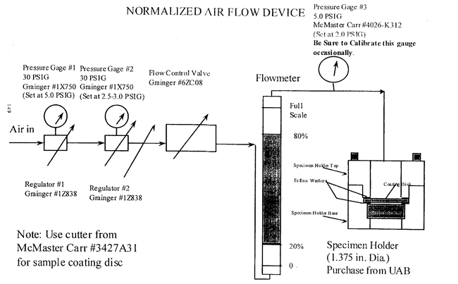
Figure 7 - Coating permeability Apparatus
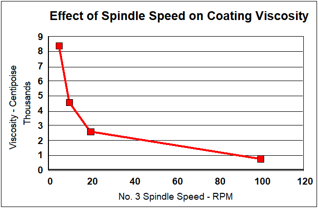
Figure 8- The Influence of Shear Rate on Coating Viscosity
Solids Content
This procedure includes weighing a sample of coating from the dip tank, drying the sample and weighing the dried sample.