Key words: LFC, thin wall, deformation
Abstract: the thin-walled parts produced by LFC process are easy to deform. By adjusting the mold splitting process, bead density, mold assembly process, coating, drying support, vibration and other process schemes, the deformation scrap rate is reduced from more than 30% to less than 0.5%, and good results are achieved.
1 Preface
Lost foam casting is known as "new casting technology in the 21st century" and "green project of casting". Lost foam casting process is considered to be a promising near net shape processing technology and cleaner production technology because of its many advantages, such as high dimensional accuracy, low surface roughness, less machining allowance, low environmental pollution, low investment and quick effect. In recent years, LFC technology has been more and more widely used in the production of truck castings. According to the author's understanding, within the scope of truck iron castings, only long bridge parts have not been successfully reported in mass production by LFC process, and other various iron castings (from the differential case, gear case, support, wheel hub, shoe, brake drum, crankshaft, engine cylinder block, cylinder head, exhaust pipe, flywheel housing, flywheel, gearbox housing, etc.) there are all reports of successful production, which has formed a trend of encirclement and suppression of the traditional sand casting.
The second foundry of Dongfeng Commercial Vehicle Co., Ltd. is a professional foundry producing truck chassis, some Engine Castings and car security parts. In order to reduce costs and meet the requirements of parts with complex structure, it has invested in the construction of a lost foam production line with an annual output of 10000 tons, which is mainly used to produce complex chassis shell parts, gearbox shell, flywheel shell, lower cylinder block and other castings.
During the commissioning and production process, the production of small gearbox, flywheel housing, reducer housing, cylindrical gear housing and other parts has been basically successful, especially the deformation has been basically controlled. However, it is very difficult to produce a thin cylindrical gear shell, and the prominent problem is the deformation of the part. In this regard, we have carried out technical research and process research.
2 product introduction and problem raising
The cylindrical gear case with thin shell (see Fig. 1) is figuratively compared to a half peanut shell with main wall thickness of 7mm, without stiffeners and full of oil passages, weighing 23.2kg, length, width and height: 495 * 237 * 181, material QT450-10. This piece was previously produced by tidal mold sand process. This piece has many oil passages and isolated heat joints. The main waste products are shrinkage porosity and air holes, and 6 sand cores are used, It can only be solved by using multiple cold irons and thermal insulation risers. The process is complex and the production cost is high.
The lost foam process basically eliminates the molding and core making process and has advantages in cost. After the lost foam process is adopted, the deformation problem has become a restrictive factor for the mass production of the part, mainly the warpage and deformation of the large flange surface. On the processing lathe, the deformation of individual parts with large deformation can be seen by the naked eye. See Fig. 2. The deformed parts are checked by marking, and the maximum deformation reaches 5.4mm, The deformation is concentrated on the flange surface around the big ring, as shown in Figure 3. The initial machining allowance of this surface is 2.5mm. At the same time, this surface is the processing positioning surface of the first processing process. Its deformation directly causes inaccurate positioning and subsequent processing deviation. In actual production, the deformation within 2.0mm is regarded as the qualified detection standard. Nevertheless, the deformation scrap rate is still as high as more than 30%.
After analysis and commissioning verification, the supporting wall thickness of the flange surface is only 7mm, there is no stiffener, and the strength and stiffness of the foam flange surface are very low. The subsequent processes such as mold making, mold assembly, dip coating and vibration will increase the deformation and cause waste products. In order to completely solve the deformation of this part, we need to start from the whole production process. On the one hand, we need to reduce the deformation caused by each process, on the other hand, we need to take measures to strengthen the strength of foam and improve the ability to resist deformation.
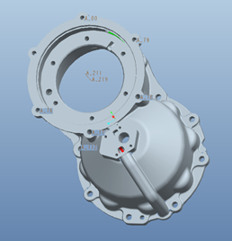
Figure 1 Product picture of cylindrical gear housing
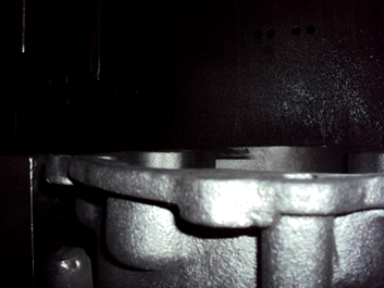
Figure 2 Deformation visible to the naked eye
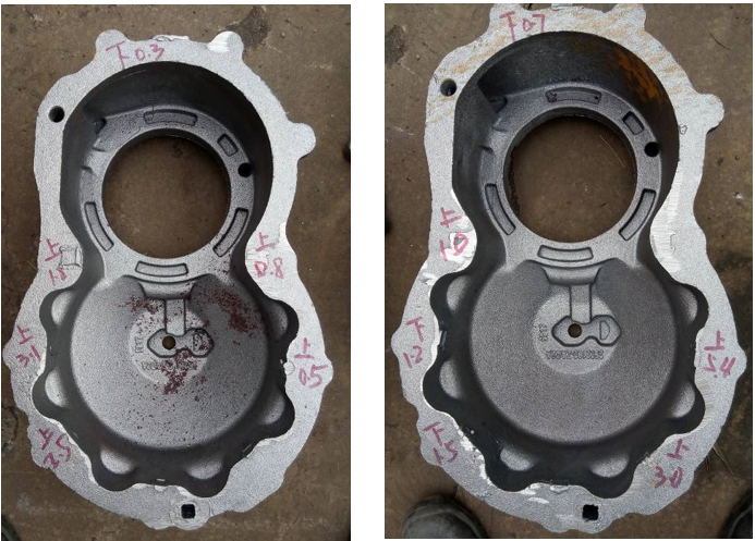
Figure 3 Checking results of the deformation dimension of the cylindrical gear shell
3 Production process and solutions
The main production process of lost foam castings is shown in Figure 1, and the deformation of the castings is concentrated in the 2-8 stages. As the prerequisite of the production process, the foam mold parting process design greatly affects the deformation, so it is the first special column. To this end, we take process measures from the above-mentioned stages.
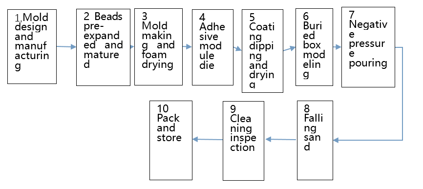
Figure 4 Main production process flow
3.1 Mold design and manufacturing
For lost foam, the strength of the foam itself fundamentally determines whether the casting is easy to deform. The strength of the foam depends on three points: product structure, parting method, and pre-release density.
The thin-walled piece has no ribs, and the foam itself is extremely easy to deform. This product is a mature product and cannot be changed in structure.
In the parting method, two methods are used before and after. The first one considers the convenience of mold making. The design idea is to split the mold in half along the sand core of the oil passage, so that the mold design and production are simple and there is no live block. However, this destroys the integrity of the Dafa surface, resulting in a decrease in the strength of the foam at this location, which makes the overall structure of the foam less rigid and easily deforms the foam.
The second priority is to consider the foam as a whole as much as possible, and at the same time make the rounded corners that affect the strength larger within the allowable range of the drawing. In view of the structural characteristics of this part, the overall core-pulling scheme is adopted for the oil passage through the flange surface to ensure the integrity of the large flange surface of the foam, ensure the strength and rigidity of the foam itself, and reduce the flange surface adhesion and avoid sticking. Avoid artificial deformation during die sticking, as shown in Figure 2, and put a new set of dies into operation.
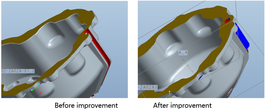
Fig. 5 change of oil passage die cutting mode
Compared with the foam produced by the two processes, the new parting scheme can be felt by hand, and the strength and stiffness of the foam are significantly improved. Under the same process, the deformation scrap rate can be reduced by about 25%.
For thin shell parts, the primary consideration in die design is to produce the die as a whole, improve the strength of the foam and provide a prerequisite for reducing deformation. At the same time, the feeding nozzle setting is considered in the die design, and the foam density is uniform.
3.2 Pre-expansion and maturation of beads
If the pre-hair density of beads is high, the strength of foam will naturally increase, but it will lead to the subsequent problems of large gas generation and foam size growth. The pre-hair density is too small, and the strength and rigidity of the foam are low. Therefore, choosing the appropriate pre-hair density is another prerequisite to determine the strength of foam. We selected the suitable pre-hair density of this part through many experiments. Different bead densities should be selected according to the product characteristics. Thin-walled parts can appropriately increase the bead density and enlarge, and thick and large parts can appropriately reduce the bead density.
3.3 Moulding and foam drying
After the process of making and taking the foam, it is found that part of the foam has been deformed, and the deformation surface is limited by bracket fixation, hoping that it can be corrected after drying, and the result is just the opposite. The reason is that the deformation of the contact part between the foam and the bracket increases due to different temperatures and drying speeds. The foam has no external force in the drying stage, the temperature is uniform, and the shrinkage and deformation are consistent.
3.4 Mucosa modeling
After the foam is dried, through our measurement, the deformation of the large plane is generally within 0.5mm, but the structural strength of the foam is low, and it is easy to cause deformation when the mucosa is assembled. For this reason, we designed a fixture with correction function, and made a mandatory foam correction fixture according to the external dimensions of the flange face. With the boss on the back of the flange face as the positioning benchmark, the boss of the flange face of the foam was nested in the fixture during mold assembly, and then the easily deformable surface was fixed with a 15mm thick annular pressure plate to ensure that the big flange was in the same plane when the wood strips were bonded and fixed, that is, to correct and prevent the warping deformation of the foam, as shown in Figure 6.
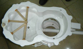
After the foam is finished in the mold assembly fixture, the foam should be reinforced and shaped, and a fan-shaped inner support structure suitable for the inner cavity of round shell castings should be adopted. The wooden strips assembled as required should be bonded with hot glue in turn to ensure the bonding is firm. After the hot glue is solidified, the foam can be taken out from the fixture, as shown in Figure 7.
In this way, on the one hand, the problems of low accuracy, cumbersome bonding, waste of wood and the like caused by the traditional well-shaped support method on the flange face are well solved. On the other hand, it can improve efficiency, division of labor and cooperation, assembly line operation, and reduce cleaning workload because there is no bonding point on the surface of large flange.
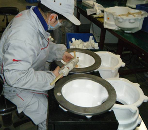
Fig. 6 group of mould fixture and its
Fig. 7 Internal support process
3.5 Coating dipping and drying
The coating stage is divided into two aspects, one is to prevent the foam from being deformed by human operation in the dipping process, the other is the coating performance.
In order to prevent the deformation of the foam during dipping, we strictly stipulated the dipping technique of employees to prevent the deformation of the foam caused by external force and coating resistance.
Generally speaking, coatings have seven main properties: strength (normal temperature and high temperature), coating and hanging (including leveling and thixotropy, etc.), air permeability, fire resistance, suspension, defoaming and smell. However, it is difficult to achieve coatings with all good indexes. For deformed parts, the paint must provide enough strength for the foam. Therefore, these performance indexes should be the strength and air permeability in the first place for easily deformed parts, especially the normal temperature strength. Increasing the coating thickness can significantly improve the strength and help to reduce the deformation caused by vibration, but increasing the coating thickness will correspondingly reduce the air permeability, resulting in the increase of carbon slag and cold insulation waste products. For this reason, nearly 10 kinds of coatings were compared and tested, and finally a suitable coating was found to solve this problem. The coating has good strength and air permeability. The coating thickness is 0.8-1.5mm after twice coating. For the flange surface which is easy to deform, an additional layer of coating is added, and the coating thickness is 2.0-2.5 mm.. For deformable parts, the strength of coating can not be overemphasized, and the surface strength is far greater than the point strength supported by die assembly.
After coating the foam, because the weight of the coating is much larger than that of the foam, it is easy to cause plastic deformation of the foam due to improper placement. The deformation of the cluster was detected, and it was found that the deformation of some cluster reached 0.8 mm. Therefore, a special support was designed for this part, and then the deformation of the cluster was detected to solve this problem. At this stage, it is important to design the appropriate placement angle and fixture. The most common mistake is to design the bracket according to experience or not to use the bracket, and the specific use effect must be judged by testing.
3.6 Buried box modeling
The core equipment of LFC is vibrating table. Our factory selects the domestic suspended vibrating table, model SYZ-04, whose structure is shown in Figure 5. It consists of a base, air springs, a workbench and a vibration motor. Eight air springs are installed on the base, and the air springs support the workbench. Two excitation motors with a power of 1.5 (kw are installed on the side of the workbench to realize one-dimensional vibration in the vertical direction. In the process of compaction, the sand box is thrown up, falling down and colliding with the bottom cone, resulting in vertical vibration, and irregular lateral vibration is generated by disorderly collision of three conical supports on the compaction table and three grooves on the sand box, thus realizing the three-dimensional vibration effect. In the process of throwing up the flask, the synchronous high-speed rotation of the vibration motor generates high-frequency vibration, and the vibration frequency can be adjusted according to the technological requirements to quickly compact the loose molding sand.
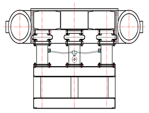
Figure 8 Vibration table
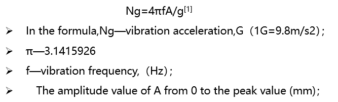
To ensure the effectiveness of vibration, the choice of vibration frequency is particularly important. Generally, 32Hz~60Hz is used. For a vibration system, the relationship between its vibration frequency, acceleration and amplitude is:
g—acceleration of gravity,m/s2。Therefore, the amplitude can be used to indicate the actual offset of the vibrated object, or the acceleration of the vibrated object, which is determined by the frequency, generally in the range of 0.2mm-1mm. The above is the standard formula for calculating the acceleration of the lost mode, but the actual vibration process is far more complicated than the formula.
When measuring the vibration acceleration and amplitude of the sand box, it is found that the acceleration of different parts of the same sand box is different, and the parameters of the same parts of different sand boxes are also different. As shown in Figure 6 and Figure 7, it can be seen that the front, back, left and right, up and down forces exerted by the cluster in the vibration process are different, some of which are less than 1g, some of which are more than 2g. Therefore, the vibration acceleration and amplitude of different parts are the same when measuring the vibrating table. It can be seen that the reason for the large deviation of vibration parameters is the poor rigidity and consistency of the sand boxes. Through dimensional marking inspection of some sand boxes, it is found that the maximum deformation of some sand boxes has reached 5mm. Therefore, all sand boxes have been reinforced and reformed to ensure the consistency of sand boxes as much as possible. According to the reformed sand box, the layered compaction process of this piece is re-determined. From the actual effect, the compaction stability has obviously improved. Each compaction time is reduced from 55 seconds to 33 seconds, and the eccentricity of the eccentric block of the motor is reduced from 110mm to 90 mm. On the premise of ensuring the compaction effect, try to reduce the vibration excitation force, shorten the compaction time and reduce the deformation caused by the compaction process.
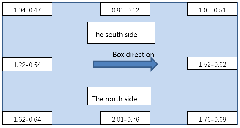
Figure 6 Acceleration and amplitude values of different parts of a sand box (data: acceleration-amplitude)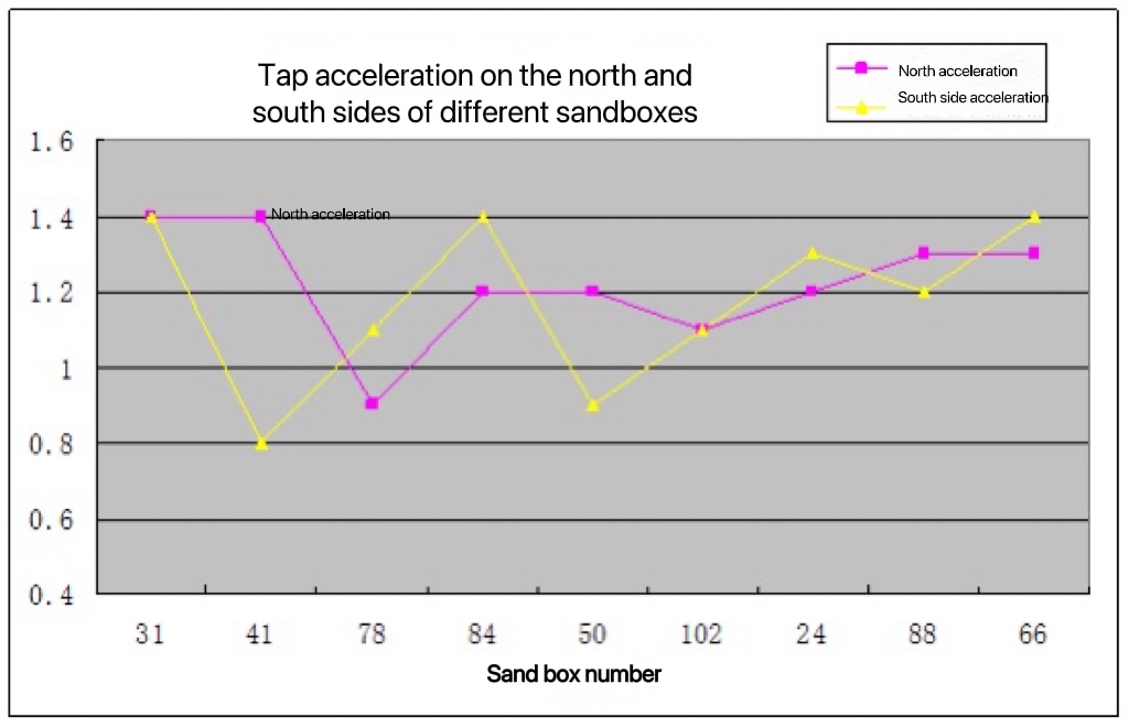
Figure 7 Acceleration changes of the same part of different sand boxes (acceleration unit: g)
3.7 Negative pressure pouring
In order to test the relationship between the holding pressure time and the deformation of the castings, the deformation of the castings at 5 different holding times of 0s, 60s, 120s, 180s, and 300s was measured after the pouring, and it was found that there was no significant difference in the deformation ratio and the amount of deformation. In other words, the holding pressure and holding time have no significant effect on the deformation of the casting.
4 Effects
By improving the debugging and tracking of the entire production process, the key factors that affect the deformation of the part are: parting process, foam, paint dipping and drying, and vibrating process. Through the adoption of the above measures, the deformed waste products have dropped linearly. From more than 30% in the previous period to less than 0.5%, the comprehensive waste is less than 5%.We believe that 0.5% of the deformed waste product is still generated in the tapping stage due to the different consistency of individual flasks.
5 Conclusion:
The lost foam elimination process is the result of a multi-pronged approach. The key lies in the attention to detail and the control of the whole process. No one measure can solve all the problems. It is necessary to rely on the comprehensive exploration of the craftsman to find a solution to the problem.