Study on preventing deformation of flywheel housing by Lost Foam Casting
Keywords:
LFC
flywheel housing
deformation
2021-12-22 17:12
41278
小中大
Key words: LFC, flywheel housing, deformation Abstract: Taking the gray cast iron flywheel housing as an example, this paper introduces the lost foam casting process and difficulties of the part, analyzes the causes of deformation defects in different parts combined with the specific structure and requirements of the part, and puts forward the corresponding countermeasures: through product structure optimization, overall foam consideration, reasonable buried box vibration process Process strengthening rib and other measures to reduce deformation and waste products.
1.Introduction Lost Foam Casting (LFC) is a new casting technology with nearly no surplus and accurate forming. It has many advantages, such as: molding sand does not need binder, casting sand falling and sand treatment system is simple, and it is easy to realize cleaner production; The casting has no parting surface and draft angle, which can make the structural design of the casting more reasonable; The casting has high dimensional accuracy, good surface finish and complex structure; wait. Therefore, it is called "new casting technology in the 21st century" and "green engineering in casting". In recent years, with the continuous breakthrough of key technologies in LFC, the growth rate of its application has accelerated. However, China's LFC technology is still in the period of technological innovation, which needs a process of technological accumulation. The flywheel housing is a cast iron piece, which is not easy to deform. It accommodates the clutch assembly, bears the weight of the transmission and acts as a fulcrum for power transmission. The flywheel housing is installed on the girder support. There are suspensions on both sides of the housing, which are fixed by bolts to prevent the flywheel housing from jumping and shifting. A movable bottom shell is installed at the bottom of the flywheel housing to facilitate disassembly and assembly of the flywheel and clutch assembly and adjustment of the clutch. A starter is also installed on the flywheel housing. It can be seen that the flywheel housing is used to bear the weight, position the engine and transmission, and place the starting parts. At present, more than 80% of the flywheel shells in China are produced by LFC process. At the initial stage of EPC project design, our factory also takes the flywheel shell as one of the main products.
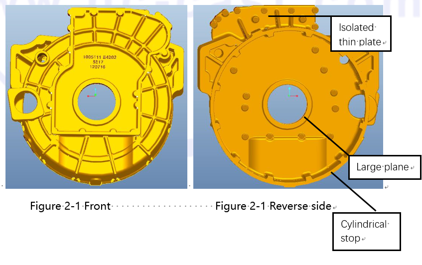
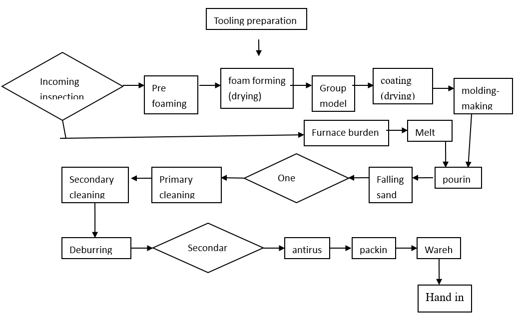
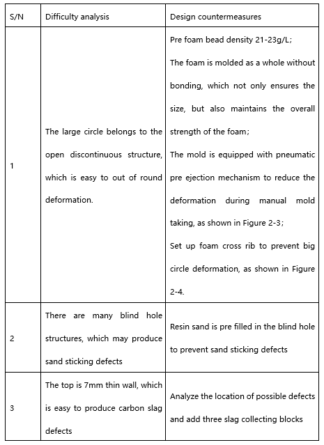
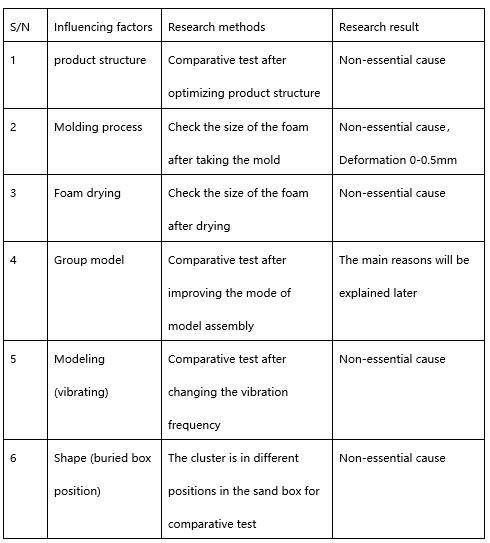
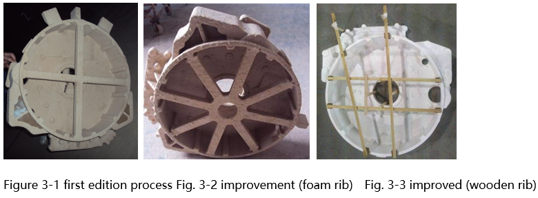
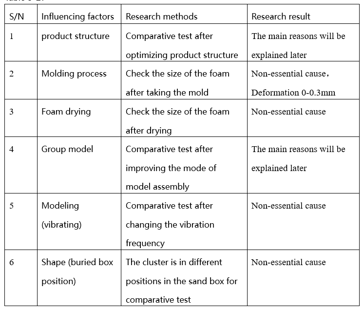
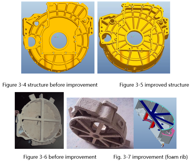
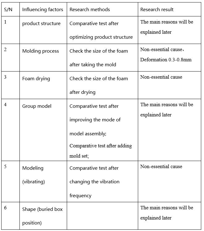
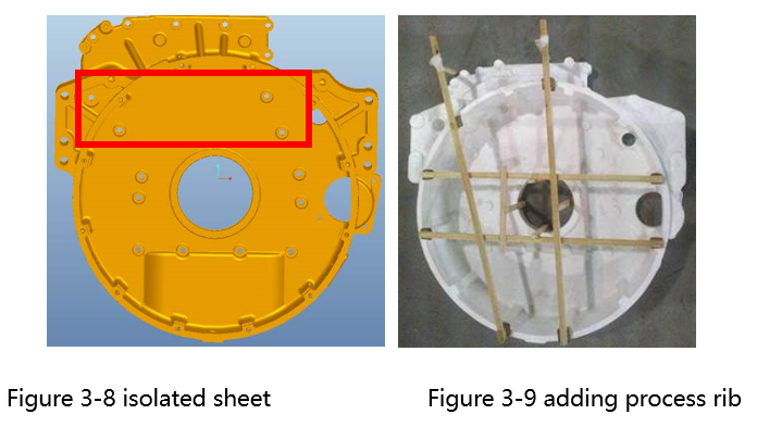
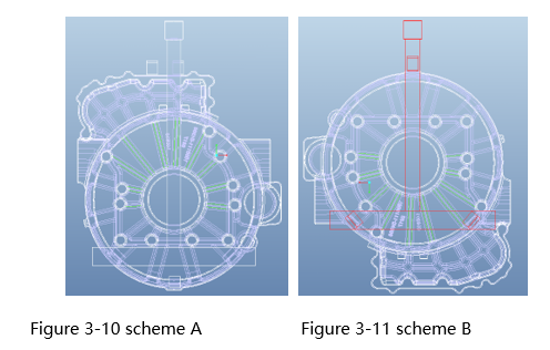
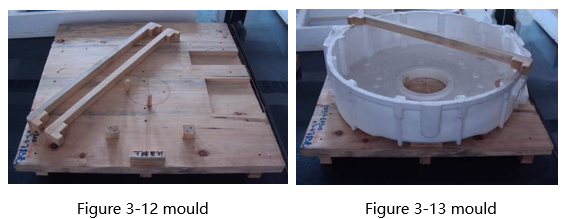
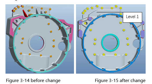
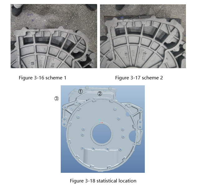
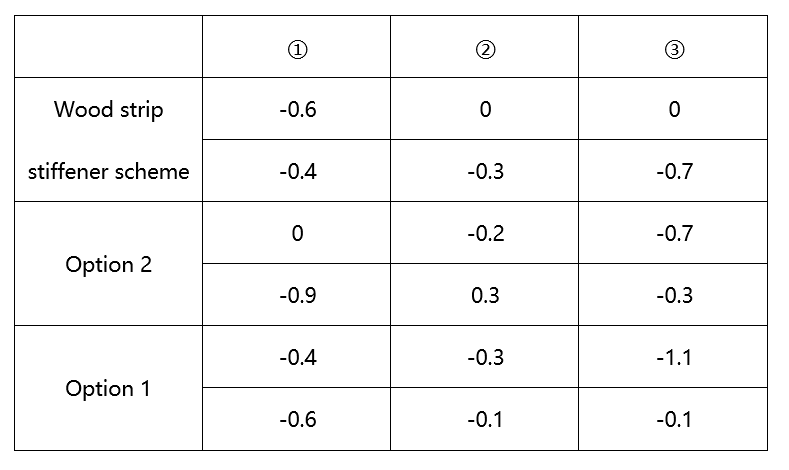
2.Lost foam process design of flywheel housing 2.1 Basic information of flywheel housing castings X7 cast iron flywheel housing, product structure with gear chamber cover, side wall with boss for sensor installation; The main wall thickness is 7mm and other wall thicknesses are 20-30mm. Figures 2-1 and 2-2 show the structure of the first edition; Outline size: large circle size ∮ 555 * 151, maximum size 626 * 637 * 160; Material: HT250; Weight: 58.3kg; 2.2 Process planning Technological process 2.3 Analysis of Difficulties in Casting 3.Research and improvement of casting technology 3.1 Casting defect analysis In the development process of the part, deformation defect is the main reason affecting the yield of the part. Of the 120 castings initially produced, only 18 can be assembled, and the rest have machining black skin or assembly interference to varying degrees. The statistics of the parts with problems are mainly concentrated in three parts (as indicated in Figure 2-2), and the causes are preliminarily analyzed: First, the outer circular stop of the flywheel housing is deformed, resulting in the processing of black skin or the minimum wall thickness of individual bosses does not meet the requirements of the drawing; The outer circular stop shell has a wall thickness of 7mm and an open structure. The foam is easy to deform in the process of forming, taking mold and dipping paint; The cluster is also easy to deform in the process of molding, sanding and vibrating. The reinforcing rib of the first edition process can not prevent deformation well. The reinforcing rib should be added to improve the overall structural stiffness of the white formwork. Second, the large plane deformation of the flywheel housing, that is, the joint surface between the flywheel housing and the engine, the deformation of which shall not exceed 2mm, otherwise the gap between the flywheel and the plane will be too large or too small, resulting in oil seal leakage or flywheel installation interference. The actual statistical results: the proportion of deformation ≥ 2mm is 67%. The plane thickness is 7mm. During the production process, it is found that the deformation mainly occurs in two processes. One is the dip coating process. The foam is buckled after dip coating. Due to the gravity of the accumulated coating on the upper part, the face is deformed inward; Second, in the process of vibration, the cluster is deformed due to the force gradient due to the movement of molding sand due to the inconsistency of compactness between internal and external molding sand; The maximum deformation of the casting measured actually reaches 4.12mm. There are two main reasons: one is that there is almost no reinforcing rib in the whole plane of the casting, that is, its structure determines its poor deformation resistance; Second, the process did not identify the risk of deformation of this face and did not take corresponding preventive measures. Therefore, the product structure and process should be improved. Third, the deformation of isolated thin plate, which will lead to black skin processing here or damage the blank surface. There are three main reasons for the deformation. One is the product structure. The thin plate extends 100mm. Although there are three small pull ribs, it is still very easy to deform in the process of mold assembly, dip coating and modeling; Second, the foam has been deformed during mold assembly, and the actual measurement is 0.3-0.8mm; Third, in the process of vibration compaction, this part is in the lower part, which is subject to large vibration force and easy to deform. 3.2 Countermeasures and result analysis of casting deformation 3.2.1 Improvement of deformation of outer circular stop of flywheel housing By analyzing the possible deformation process in LFC process, the following influencing factors are studied and the main reasons are determined: Table 3-1: The "ten" shaped foam rib is adopted in the first version of the process, as shown in Figure 3-1. With the improved process (two types, FIG. 3-2 and Fig. 3-3), the maximum deviation of the outer circle diameter of the casting is controlled from the previous 1.9-3.8mm to ≤ 1.2mm, meeting the processing and assembly requirements; The main reason is that after adding reinforcing ribs, the ability of foam and cluster to resist deformation is improved, so the deformation is reduced. 3.2.2 Improvement of deformation of large plane of flywheel housing By analyzing the possible deformation process in LFC process, the following influencing factors are studied and the main reasons are determined: Table 3-2: According to the reasons, two measures are mainly taken. First, starting from the product structure, the reinforcing rib is added in the plane to improve its stiffness (compared with figures 3-4 and 3-5), that is, the reinforcing rib radiating outward from the center is added on one side. As a result, the proportion of deformation ≥ 2mm is 22.2%, which is significantly lower than that in the previous period; The second is to increase the process reinforcing rib to further increase the stiffness of the foam while ensuring the size (Fig. 3-6, 3-3 and 3-7); Through the experiment, the maximum deformation of this surface is 0.8mm, which meets the requirements of the drawing. The main reason is still the function of reinforcing rib, one is the reinforcing rib designed for product, the other is the reinforcing rib designed for casting process. 3.2.3 Study on deformation of isolated thin plate By analyzing the possible deformation process in LFC process, the following influencing factors are studied and the main reasons are determined: Table 3-3:: (1)Influence of process stiffener on deformation: As shown in Figure 3-8, before any process rib is made in the first version design, the proportion of deformation ≥ 1mm is 100%, and the maximum deformation is 3mm; As shown in Figure 3-9, after adding the process reinforcing rib, the deformation ratio ≥ 1mm is less than 30%, and the maximum deformation is 1.3mm; (2)Influence of isolated thin plates at different positions in the sand box on deformation:: In this paper, two embedding methods are designed as shown in Figure 3-10 and figure 3-11. Eight pieces are formed in each of the two methods (both with wood strip process reinforcing ribs). The deformation (maximum deformation) is compared. The statistical results are shown in table 3-4. It can be seen that the deformation of the isolated thin plate in the upper part of the sand box is significantly lower than that in the lower part of the sand box. The first reason is that the force of molding sand at different heights on the cluster is different during the compaction process. The closer it is to the lower part of the sand box, the greater the force of molding sand on the cluster during the compaction filling process, so the deformation of the thin plate is large when it is located at the lower part of the sand box; The second is that the molding sand sinks continuously during the compaction process, and the force on the thin plate is large when it is in the lower part. Table 3-4: deformation statistics (3)Effect of mold assembly on deformation Because the thin plate will be slightly deformed when the foam is assembled, about 0.3-0.8mm; In order to ensure the dimensional stability of the foam in the bonding process, a set of mould is designed and manufactured, as shown in Fig. 3-12 and 3-13. Based on the joint surface between the flywheel housing and the cylinder block, the wooden strip is bonded after the back of the thin plate is in contact with the plane of the mould, which can correct the foam and prevent deformation at the same time. It is measured that there is almost no deformation after the foam is bonded to the wooden strip. Therefore, designing a reasonable mold assembly mould to eliminate the deformation of the foam in the mold assembly process can reduce the deformation of the casting. (4)Influence of structure on deformation of thin plate Before the change, as shown in Figure 3-14, the structural thin plate extends 100mm. Although there are pull ribs, it is still very easy to deform in the process of mold assembly, dip coating and modeling. Even if the process reinforcing ribs are added, 30% of the processed parts will damage the body; After the change, as shown in Figure 3-15, the proportion of deformation ≥ 1mm is about 10% in the same process. The main reason is that it is changed to a two-stage structure. There are reinforcing ribs behind the first stage, which are connected with the main body. At the same time, it is equivalent to shortening the extension length of isolated thin plate, which is conducive to reducing deformation. The author also tries to further optimize the improved structure, and designs the following two schemes, FIG. 3-16 and 3-17. The reinforcing rib is added on the front, and the deformation of three positions of the thin plate is counted. Fig. 3-18, the actual results are shown in table 3-5. It can be seen that these two changes have little effect on the deformation. The author analyzes and believes that due to the downward deformation direction of the rib, It means that the external force is greater than the tensile stress that the reinforcing rib can bear. If the reinforcing rib bearing compressive stress can be set on the back at the same time, the effect of resisting deformation should be very good. Unfortunately, the author has not carried out the experiment Table 3-5:
4.Conclusion After the above improvement, the deformation scrap rate of this part is ≤ 2%. To sum up, for the deformation of flywheel housing parts, in addition to the conventional improvement of foam bead density and overall molding of foam, the following measures are mainly taken to avoid: (1)To improve the rigidity of the foam itself, first, optimize the casting structure during product design. Due to the particularity of LFC process, in addition to considering the requirements of traditional casting structure, the most important point should be to prevent foam deformation, such as setting necessary reinforcing ribs, mutual involvement as a whole, etc; The second is to design appropriate process reinforcing ribs in casting process design to improve the overall strength of foam cluster, so as to reduce its deformation in mold assembly, dip coating, modeling and transportation; (2)The design of appropriate mold assembly mould can be used to correct the deformed foam on the one hand, and ensure the size and no deformation in the mold assembly process on the other hand;; (3)The cluster embedding box process shall be reasonably designed. For the parts easy to deform, it shall be located in the middle and upper part of the sand box as far as possible on the basis of ensuring the filling of molding sand. After the above improvement, the deformation scrap rate of this part is ≤ 2%. In the follow-up, the causes will be found and improved from the processes of coating dipping, drying, sanding and cooling.
Related downloads
Study on preventing deformation of flywheel housing by Lost Foam Casting.pdf