Keywords : lost mode、 Blind hole、Box collapse、 Liftboard、 Pallet
Abstract : In view of the fact that blind hole in lost foam casting is easy to collapse, this paper summarizes the methods to prevent blind hole collapse in lost foam casting in production practice, and puts forward a very effective new method of lifting plate and supporting plate to prevent box collapse.
With the development of lost foam casting technology. More and more enterprises use this technology to produce more and more products. No longer just automobile industry gearbox, clutch shell castings. Some cast steel joints used in large construction venues also adopt LFC technology. The cast steel joint structure has deep blind holes and different directions, which converge at an intersection. In the production of castings with multiple blind holes, box collapse is a key problem often encountered. Solving the problem of box collapse is an important task for LFC workers.
1 Main Causes of Blind Hole Collapse in Lost Foaming Die
In lost foam casting production, castings with blind hole structure are often encountered. As shown in Fig. 1, for the model of this blind hole structure, when the box is assembled, the needs of sanding and shocking are considered. The blind hole of the model should generally be oriented to the top or above the oblique. Sometimes, due to structural reasons, a casting model has multiple blind holes and has to be oriented to the side or below the oblique. In the pouring process, due to the bottom-up filling of liquid metal, the foam mold at the lowest part first vaporizes and loses its support for the dry sand mold. The metal liquid has not come to fill the blind hole under the plastic foam original possession of the whole space, when the vaporized plastic foam gas under the action of negative pressure, is pumped into the blind hole area filled with dry sand, due to the rapid rise of the temperature inside the blind hole, and the resistance of the internal sand on the air flow. The negative pressure pressure field at the bottom of the blind hole increases rapidly, and its instantaneous value changes from the normal value of about ﹣0.05 MPa before pouring to about ﹣0.02 MPa, and even close to the atmospheric pressure value. The dry sand in the blind hole is friction produced by a negative pressure of about ﹣0.05 MPa. Can offset the gravity of dry sand. However, the loss of support force after foam vaporization and the increase of negative pressure value lead to the decrease of friction between sand particles, which instantly causes the sand in the blind hole to sink and collapse.
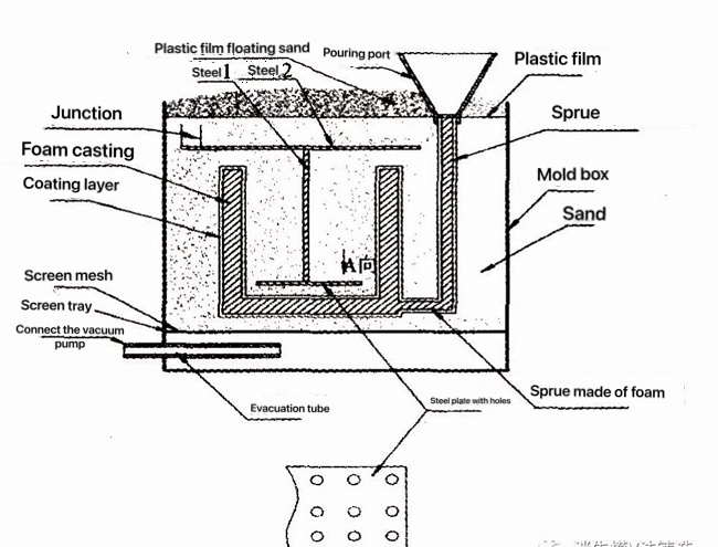 Fig 1 Schematic diagram of lifting plate structure for preventing blind hole collapse
2 Methods for preventing box collapse by existing technologies
2.1 Increasing the negative pressure according to the needs of casting structure.
The negative pressure is increased from -0.05 MPa to -0.07 MPa, which has a certain effect on preventing casting cavity collapse. But it remains unreliable for large, deeper blind holes. On the other hand, the negative effect of increasing the negative pressure is higher requirements for the coating layer, because increasing the negative pressure, the coating is easy to break and the probability of sanding defects is significantly improved. Therefore, the negative pressure during pouring should be comprehensively considered.
2.2 Stable blind hole pressure field
The negative pressure hose is inserted into the blind hole and buried in the dry sand of the blind hole, which should be close to the root of the blind hole to the maximum extent. Connect the negative pressure hose directly with the negative pressure pipe. The purpose is that in the instant of foam mold gasification, a large number of gas is pumped into the blind hole. Due to the role of negative pressure hose, the gas entering the blind hole is quickly extracted, which stabilizes the negative pressure field and reduces the possibility of box collapse. The disadvantage is that the negative pressure hose system is complex and difficult to operate, and the effect is not satisfactory for large and deep blind holes. The collapse still cannot be cured.
2.3 Blind hole filling with resin sand
Filling and curing with resin sand in blind hole can effectively prevent blind hole from collapse. However, the disadvantage is that it is necessary to equip with a sand mixer. If the filled resin sand blows CO to harden, it is also a problem use the remaining molding sand for storage time and storage environment. The operation procedure is troublesome. If self-hardening resin sand is used. Blended molding sand can be used for long enough time, the amount and mixing amount should be as consistent as possible to reduce waste. Some factories use sodium silicate sand core, there are still these problems, the sand cleaning is more difficult than resin sand.
2.4 Reducing the permeability of coatings inside blind holes
More fine coating aggregate is used to increase the thickness of coating inside the blind hole. The purpose is to reduce the air permeability of the coating inside the blind hole. It can greatly reduce the number of gas pumped into the blind hole by foam mold gasification, so that the negative pressure value inside the blind hole can be relatively stable or close to the original level. So as to maintain enough friction between sand, reduce the possibility of collapse.
2.5 Reduce the number of foam models in sand tank
In the group box, easy to collapse the box model, in the same sand box, can reduce the number of models placed. In this way, the total amount of instantaneous gas generated during the gasification of foam mold during pouring can be reduced. In this way, the burden of suction negative pressure in the sand box is reduced. The negative pressure in the sand box changes little, and the negative pressure in the blind hole is relatively stable. This reduces the possibility of collapse.
3 A New Method to Prevent Blind Hole Collapse of Lost Foaming Die
3.1 Set the ' 工 ' type tray
(1) The ' 工 ' type lifting plate structure, as shown in Figure 1.
Figure 1 is the schematic diagram of casting blind hole model and lifting plate structure. The lower part of circular steel pipe 1 is welded with the conformal stripper, and the shape of the conformal stripper is determined by the shape of the blind hole. The size of the tray is slightly smaller than that of the blind hole. In general, the tray is tens of millimeters smaller than the blind hole. There are many holes with a diameter of 30 mm drilled on the lifting plate, and the hole spacing is about 50 t urn. The real-time sand can be moved down through the hole to meet the sand compaction of the bottom space of the lifting plate in the blind hole. On the other hand, due to the existence of holes. The sand up and down the tray forms a whole. Circular steel tube 1 and circular steel tube 2 are welded firmly. The diameters of the two are determined according to actual needs. In principle, the larger the blind hole is, the larger the diameter is. Circular steel tube 2 requires a certain bending strength to meet the stress requirements. According to the size of the model, the circular steel tube 2 with enough length is selected, so that both ends of the circular steel tube 2 can extend out of the opening of the foam model.A thin steel plate with a diameter of about 100 i nl n is welded at both ends of the circular steel tube 2, and the thickness of the steel plate is 2 mm ~ 4 mm. These two steel plates are horizontally positioned.
(2) Principle of ' 工 ' type anti-collapse box
When the metal liquid enters the cavity through the direct gate, the gas produced by the foam mold at the bottom is first vaporized and pumped into the blind hole. The gas passes through the hole of the lifting plate and the gap between the lifting plate and the surrounding of the foam mold, assuming that the negative pressure value in the blind hole increases rapidly. The gas flows from the blind hole to the vacuum pump. Once the friction caused by the negative pressure of the sand inside the blind hole is reduced to the gravity that cannot be resisted by the sand, the sand on the upper part of the lifting plate tends to sink due to the gravity. The round steel plate welded at both ends of round steel pipe 2 is to increase the support area. The upward force on the lifting plate can completely offset the gravity of sand inside the blind hole and reliably inhibit the collapse of the box. A very small amount of sand below the lifting plate does not cause collapse because the coating strength of the foam mold can fully support the gravity of such a small amount of sand.
3.2 Plate prevents blind hole collapse of lost foam die
(1) Pallet structure
For the case where the blind hole of the foam die faces upward or laterally inclined, we adopt the bracket structure, as shown in Figure 2. The left half of Figure 2 is a tray 1 placed at the bottom of the horizontal blind hole. The shape of bracket 1 and the bottom of blind hole follow the shape. If the blind hole is circular, the tray is arc-shaped and follows the foam mold. The thin sand layer between the bracket 1 and the foam mold is about 30 mm. The thickness of the bracket 1 is determined according to the size of the foam mold, and generally 2 mm – 4 mm is appropriate. Several small holes of 30 mm in diameter are also drilled on pallet 1. The hole spacing is about 50 mr I. It is worth emphasizing that the bracket 1 should be extended to a length and degree outside the blind hole, and the length out of the blind hole accounts for about one third of the total length to ensure the leverage of the bracket 1 structure. In the right half of Figure 2, a tray 2 is set up in the case of a blind hole opening pointing upwards. The structural shape, size and determination principle of tray 2 and tray 1 are basically the same. The length outside the blind hole of tray 2 can be appropriately shortened to about a quarter of the full length of tray 2.
Fig 1 Schematic diagram of lifting plate structure for preventing blind hole collapse
2 Methods for preventing box collapse by existing technologies
2.1 Increasing the negative pressure according to the needs of casting structure.
The negative pressure is increased from -0.05 MPa to -0.07 MPa, which has a certain effect on preventing casting cavity collapse. But it remains unreliable for large, deeper blind holes. On the other hand, the negative effect of increasing the negative pressure is higher requirements for the coating layer, because increasing the negative pressure, the coating is easy to break and the probability of sanding defects is significantly improved. Therefore, the negative pressure during pouring should be comprehensively considered.
2.2 Stable blind hole pressure field
The negative pressure hose is inserted into the blind hole and buried in the dry sand of the blind hole, which should be close to the root of the blind hole to the maximum extent. Connect the negative pressure hose directly with the negative pressure pipe. The purpose is that in the instant of foam mold gasification, a large number of gas is pumped into the blind hole. Due to the role of negative pressure hose, the gas entering the blind hole is quickly extracted, which stabilizes the negative pressure field and reduces the possibility of box collapse. The disadvantage is that the negative pressure hose system is complex and difficult to operate, and the effect is not satisfactory for large and deep blind holes. The collapse still cannot be cured.
2.3 Blind hole filling with resin sand
Filling and curing with resin sand in blind hole can effectively prevent blind hole from collapse. However, the disadvantage is that it is necessary to equip with a sand mixer. If the filled resin sand blows CO to harden, it is also a problem use the remaining molding sand for storage time and storage environment. The operation procedure is troublesome. If self-hardening resin sand is used. Blended molding sand can be used for long enough time, the amount and mixing amount should be as consistent as possible to reduce waste. Some factories use sodium silicate sand core, there are still these problems, the sand cleaning is more difficult than resin sand.
2.4 Reducing the permeability of coatings inside blind holes
More fine coating aggregate is used to increase the thickness of coating inside the blind hole. The purpose is to reduce the air permeability of the coating inside the blind hole. It can greatly reduce the number of gas pumped into the blind hole by foam mold gasification, so that the negative pressure value inside the blind hole can be relatively stable or close to the original level. So as to maintain enough friction between sand, reduce the possibility of collapse.
2.5 Reduce the number of foam models in sand tank
In the group box, easy to collapse the box model, in the same sand box, can reduce the number of models placed. In this way, the total amount of instantaneous gas generated during the gasification of foam mold during pouring can be reduced. In this way, the burden of suction negative pressure in the sand box is reduced. The negative pressure in the sand box changes little, and the negative pressure in the blind hole is relatively stable. This reduces the possibility of collapse.
3 A New Method to Prevent Blind Hole Collapse of Lost Foaming Die
3.1 Set the ' 工 ' type tray
(1) The ' 工 ' type lifting plate structure, as shown in Figure 1.
Figure 1 is the schematic diagram of casting blind hole model and lifting plate structure. The lower part of circular steel pipe 1 is welded with the conformal stripper, and the shape of the conformal stripper is determined by the shape of the blind hole. The size of the tray is slightly smaller than that of the blind hole. In general, the tray is tens of millimeters smaller than the blind hole. There are many holes with a diameter of 30 mm drilled on the lifting plate, and the hole spacing is about 50 t urn. The real-time sand can be moved down through the hole to meet the sand compaction of the bottom space of the lifting plate in the blind hole. On the other hand, due to the existence of holes. The sand up and down the tray forms a whole. Circular steel tube 1 and circular steel tube 2 are welded firmly. The diameters of the two are determined according to actual needs. In principle, the larger the blind hole is, the larger the diameter is. Circular steel tube 2 requires a certain bending strength to meet the stress requirements. According to the size of the model, the circular steel tube 2 with enough length is selected, so that both ends of the circular steel tube 2 can extend out of the opening of the foam model.A thin steel plate with a diameter of about 100 i nl n is welded at both ends of the circular steel tube 2, and the thickness of the steel plate is 2 mm ~ 4 mm. These two steel plates are horizontally positioned.
(2) Principle of ' 工 ' type anti-collapse box
When the metal liquid enters the cavity through the direct gate, the gas produced by the foam mold at the bottom is first vaporized and pumped into the blind hole. The gas passes through the hole of the lifting plate and the gap between the lifting plate and the surrounding of the foam mold, assuming that the negative pressure value in the blind hole increases rapidly. The gas flows from the blind hole to the vacuum pump. Once the friction caused by the negative pressure of the sand inside the blind hole is reduced to the gravity that cannot be resisted by the sand, the sand on the upper part of the lifting plate tends to sink due to the gravity. The round steel plate welded at both ends of round steel pipe 2 is to increase the support area. The upward force on the lifting plate can completely offset the gravity of sand inside the blind hole and reliably inhibit the collapse of the box. A very small amount of sand below the lifting plate does not cause collapse because the coating strength of the foam mold can fully support the gravity of such a small amount of sand.
3.2 Plate prevents blind hole collapse of lost foam die
(1) Pallet structure
For the case where the blind hole of the foam die faces upward or laterally inclined, we adopt the bracket structure, as shown in Figure 2. The left half of Figure 2 is a tray 1 placed at the bottom of the horizontal blind hole. The shape of bracket 1 and the bottom of blind hole follow the shape. If the blind hole is circular, the tray is arc-shaped and follows the foam mold. The thin sand layer between the bracket 1 and the foam mold is about 30 mm. The thickness of the bracket 1 is determined according to the size of the foam mold, and generally 2 mm – 4 mm is appropriate. Several small holes of 30 mm in diameter are also drilled on pallet 1. The hole spacing is about 50 mr I. It is worth emphasizing that the bracket 1 should be extended to a length and degree outside the blind hole, and the length out of the blind hole accounts for about one third of the total length to ensure the leverage of the bracket 1 structure. In the right half of Figure 2, a tray 2 is set up in the case of a blind hole opening pointing upwards. The structural shape, size and determination principle of tray 2 and tray 1 are basically the same. The length outside the blind hole of tray 2 can be appropriately shortened to about a quarter of the full length of tray 2.
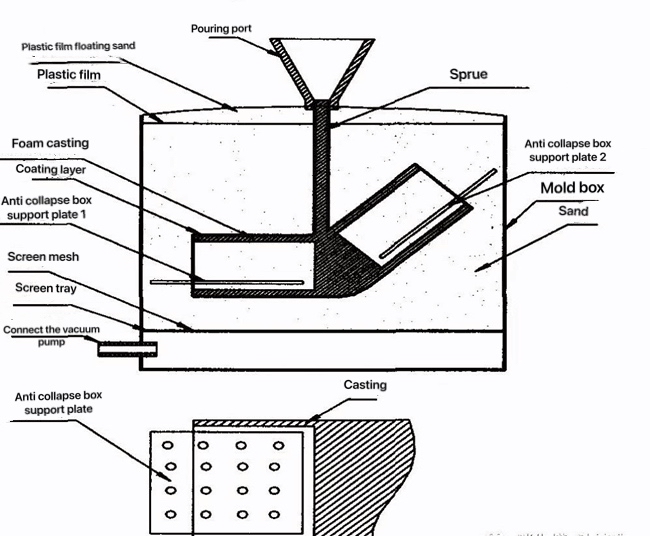 Figure 2 Scaffold schematics for preventing box collapse
(2) Principle of tray preventing collapse
When the metal liquid enters the cavity through the direct gate, the gas produced by the foam mold at the bottom is first vaporized and pumped into the blind hole.The gas passes through the hole of the lifting plate and the gap between the lifting plate and the surrounding of the foam mold.It is assumed that the negative pressure value in the blind hole increases rapidly.The gas flows from the blind hole to the vacuum pump.Once the friction caused by the negative pressure of the sand inside the blind hole is reduced to the gravity that cannot resist the sand, the tray 1 must hinder the sand sinking inside the blind hole, especially because the tray 1 extends out of the blind hole.The section of the face can stably prevent the tray 1 from moving upward and downward. That prevents the collapse of the box, and inhibits the ' core drift '. Practice has proved that it is very reliable.
Similarly, the principle of tray 2 in the right half of Figure 2 to prevent box collapse is similar to tray 1. A section outside the blind hole also has the dual role of preventing box collapse and ' core drift '. This is not redundant.
4 Concluding remarks
The method of eliminating the collapse of the mold casting hole is also applicable to the V method molding process.
Figure 2 Scaffold schematics for preventing box collapse
(2) Principle of tray preventing collapse
When the metal liquid enters the cavity through the direct gate, the gas produced by the foam mold at the bottom is first vaporized and pumped into the blind hole.The gas passes through the hole of the lifting plate and the gap between the lifting plate and the surrounding of the foam mold.It is assumed that the negative pressure value in the blind hole increases rapidly.The gas flows from the blind hole to the vacuum pump.Once the friction caused by the negative pressure of the sand inside the blind hole is reduced to the gravity that cannot resist the sand, the tray 1 must hinder the sand sinking inside the blind hole, especially because the tray 1 extends out of the blind hole.The section of the face can stably prevent the tray 1 from moving upward and downward. That prevents the collapse of the box, and inhibits the ' core drift '. Practice has proved that it is very reliable.
Similarly, the principle of tray 2 in the right half of Figure 2 to prevent box collapse is similar to tray 1. A section outside the blind hole also has the dual role of preventing box collapse and ' core drift '. This is not redundant.
4 Concluding remarks
The method of eliminating the collapse of the mold casting hole is also applicable to the V method molding process.